This informative video introduces the easy to install wingman booster that effectively increases your range and reception eliminating the need to invest in another rv tv antenna.
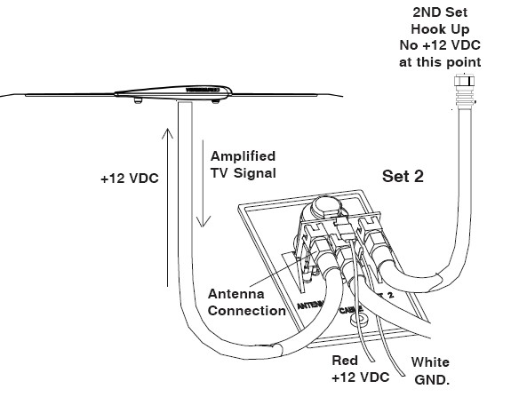
Rv tv antenna booster wiring diagram.
Learn about satellite tv for rv.
Advantages for the rvers they need a service which can allow them to watch tv in the most comfortable condition whether they are driving on the road.
This system runs 12 volt power up the coax to the antenna mounted amplifier and allows tv signal back down.
The circuit shown here is of a tv antenna booster based on the transistor bf180.
Tips and tricks on using a rv antenna bosster.
Rv antenna diagram rv antenna wiring diagram wiring diagram pertaining to winegard rv antenna parts diagram image size x px and to view image details please click the image.
Here is a picture gallery about winegard rv antenna parts diagram complete with the description of the image please find the image you need.
Wall plate power supply provides 12vdc to antenna and 12 volt receptacle as well as antenna signals to two tv sets.
Most but not all present day winegard rv antennas have the amplifier built into them for these you need a power supply block.
Turn the tv antenna power booster located inside the unit to the off position in some units turn the booster to the cable position.
Depending on the tv set it may be necessary to reprogram the tv from air to cable.
Turn the tv antenna power booster located inside the unit to the off position in some units turn the booster to the cable position.
The wiring for your tvs comes in from a jack on the exterior connects to the booster and then splits off to the other tv locations in the rv.
The circuit operates in the uhf band and has a gain of 15db.
The input signal is fed to the emitter of q1 through this.
Function when saying to satellite tv service for rvers most of them knew that there are many channels of television to watch anywhere.
With the advent of new technologies like hdtv and digital tv rvers often ask whether they need a new rv tv antenna.
Rv antenna with outdoor receptacle for tv set and cable input.
Capacitors c2 c3 c4 c5 and inductors l3 l4 forms a uhf band pass filter.
Turn the tv to the appropriate channels to receive cable.
Each part should be set and linked to different parts in particular manner.
Otherwise the arrangement will not function as it should be.
Unlike homes where the splitters are usually located in attics or basements where you can see them rv manufacturers put the splitters in the walls behind the jacks.
For the non amplified antenna you ll need a amplifier block.